|
|
Newsletter Jul 2026 | Menu of
Newsletters
|
Chip-based
Atomic Force Microscopy Sets New Expectations
|
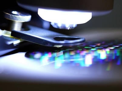
Minus
K Vibration Isolation under a MicroChip Based ICSPI Redux AFM, integrating
components such as cantilevers and sensing architecture, into a single
microchip using MEMS (micro-electromechanical systems)
technology.
|
Since its commercial
introduction in 1985, the atomic force microscope (AFM) has become one of the
foremost tools for imaging microstructures on the micrometer and nanometer
scale. Capable of revealing sample details down to the atomic level, with
resolution on the order of fractions of a nanometer, the AFM is instrumental
for imaging in an array of applications, such as in materials science and
semiconductor fields, and can even be involved in the manipulation of atoms and
nano-sized structures on a variety of surfaces.
The atomic force
microscope utilizes a sharp tip (probe), with a radius of curvature on the
order of nanometers, attached to the end of a tiny cantilever used to scan
across a sample surface to image its topography and material properties. When
the tip is brought into proximity of a sample surface, forces between the tip
and the surface lead to a deflection of the cantilever. This deflection is
recorded using, typically, a laser beam that is reflected from the top surface
of the cantilever to a photo-sensitive detector. The resultant change of
position of the cantilever permits characteristics, such as mechanical,
electrostatic, magnetic, chemical and other forces to be precisely measured by
the AFM. These characteristics are displayed in a three-dimensional surface
profile of the sample (in the X, Y and Z axes)-an advantage that the microscope
can provide compared with other microscopy techniques..
AFM
challenges
AFM is widely recognized as a powerful, yet complex and
time-consuming technique for nanoscale imaging and measurement. Traditional,
legacy AFM requires highly skilled operators and intensive manual labor,
operating at slow scanning speeds, to achieve high-resolution nanoscale
imaging. Operators often spend significant time manually loading cantilever
probes using tweezers and aligning lasers for optical
detection.
Manually positioning the probe close enough to the surface
without crashing requires skill, patience, and time. Operation often requires
specialized PhD-level training to manage tip-sample dynamics of finicky silicon
probes and complex tuning to avoid tip crashes or artifacts. New users often
struggle with breaking expensive, delicate probes, making training a slow and
costly process.
Traditional AFM scanning is slow, often taking several
minutes to acquire a single, high-quality image. Because the probe cannot scan
and manipulate a sample simultaneously, multi-step modifications are
exceptionally slow. Further complicating AFM operation, high-resolution
scanning is easily influenced by noise, necessitating repeated scans or
intensive post-processing.
Recent advancements in AFM
technology
Within the past decade, however, research into AFM design has
demonstrated success with improving scanning performance. While traditional AFM
remains a demanding technique, these innovations are rapidly making the
technology more accessible and faster for users.
Recent developments
with AFMs now make possible automated sample probing, laser-free alignment, and
one-click motorized approaches to the sample. Researchers are applying deep
learning to automate image reconstruction, improve signal-to-noise ratios, and
speed up data acquisition.
Of particular interest is the introduction of
chip-based AFM. Data collection speeds can now be achieved that are an order of
magnitude faster than traditional AFMs, enabling broader use in manufacturing
and scientific research.
Chip-based AFM
Chip-based AFM refers
to integrating AFM components, like cantilevers and sensing architecture, onto
a single microchip using MEMS (micro-electromechanical systems) technology,
creating a miniaturized, and more robust system for nanoscale imaging and
sensing..
It provides advantages like reduced size, simpler operation,
and higher speed. The on-chip design removes the need for manual laser
alignment and complex probe exchanges, as sensors and actuators are pre-aligned
during manufacturing.
Chip-based AFMs were first commercialized in 2007
by ICSPI, with the goal of bringing fast, powerful, and easy-to-use nanoscale
metrology to everyone. The company has pushed the boundaries of nanoscale
imaging, and semiconductor metrology and inspection with the introduction of
its nGauge and Redux AFM systems.
“Frustrated by the poor
versatility, complexity and slow speeds of traditional instruments, ICSPI has
been focused on resetting the expectations for nanoscale imaging with intuitive
AFM systems,” said Qianshu Wang, Application Engineer at ICSPI. “Our
Redux AFM, for example, reduces setup time to as little as three minutes,
eliminating manual laser alignment. It is a motorized, automated AFM that can
precisely navigate to regions of interest on the
sample.”
Sensor-integrated AFM Chip
AFM-on-a-chip
technology uses an integrated MEMS actuator and a piezoresistive sensor to move
the tip and detect cantilever deflection that provides a fully automatic,
one-click approach from the tip to the sample. The precise XYZ scanners and
positioning sensors are integrated onto a single 1mm x 2mm chip.
The tip
typically oscillates (taps) on the surface, and the changes in oscillation
(amplitude, phase) are measured to map topography. The on-chip components
provide robust feedback enabling precise tip-sample interaction. “The AFM
probes are securely bonded onto the end of a carrier printed circuit board
(PCB), making them robust and durable for extended use,” said Wang.
“They can be handled by hand, provided the probe itself is not directly
contacted or subjected to mechanical stress.”
Two different types
of tips are available depending on resolution requirements: a) high-aspect
ratio diamond-like carbon (DLC) tips for high-resolution and general-purpose
imaging; and b) alumina wedge (WDG) tips for coarse imaging, training and
step-height measurements.
Aluminum Wedge (WDG) Tips?
Well
suited for coarse imaging, training and step heights. The native oxide
(alumina) of aluminum is a low surface energy material. Alumina is a durable
material that enables hundreds or thousands of scans without noticeable
degradation in scan quality.
Vibration Isolation
Typically,
AFMs need to be used in the basements of buildings with a dedicated metrology
room to minimize vibrations. The Redux AFM, however, is lighter than
traditional AFMs, so it is uninfluenced by much of the low frequency noise that
commonly causes issues with AFM scans. However, not all low-frequency
vibrations are cancelled out. Redux AFMs still require vibration isolation to
guarantee their performance..
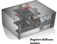
For this purpose, ICSPI chose
Negative-Stiffness vibration isolators (by Minus K) because they
do not require air or electricity, and their compact size and portability makes
them a good fit for small-form AFMs in different environments.
Full
article...
|
|
Featured Product:
Compact CM-1 Low Frequency
Vibration Isolator
 |
| |
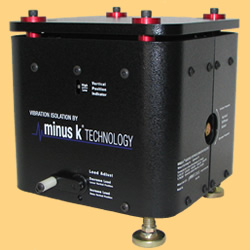
The
CM-1
is a compact high capacity, low-frequency negative-stiffness isolator. As with
all Minus K isolators, they are completely passive and use no air or
electricity. The isolators can be combined into multi isolator systems to
support heavy payloads while taking up very little room themselves.
-
Dimensions: 7.875" W x 7.875" D x 8.5" H (200mm W x 200mm D x 216mm H)
- Vertical
natural frequency of 1/2 Hz or less can be achieved over the entire load range.
- Horizontal natural
frequency is load dependent. 1/2 Hz or less can be achieved at or near the
nominal load.
Pricing &
sizes for CM-1
Specifications
(pdf) | | |
|
|
|
|

Minus K
Educational Vibration Isolator Giveaway
2022 Winner Research
Project
Optical
Coherence Elastography - Pushing the Boundaries
of Real-Time Strain and
Elasticity Imaging of Biological Tissue
Optical coherence
elastography (OCE) holds great promise for detecting and monitoring the altered
mechanical properties of strain and elasticity with biological tissue that
accompanies many clinical conditions and pathologies, particularly in cancer,
cardiovascular disease and eye disease. Researchers at UC Irvine's Beckman
Laser Institute are pushing the research envelope with OCE application, with
the assistance of Negative-Stiffness vibration isolation.
|
|
Tissue exhibits
varying degrees of viscoelasticity (time-dependent response to a load),
poroelasticity (presence of fluid-filled pores or channels), and anisotropy (a
physical property that has a different value when measured in different
directions), as well as a nonlinear relationship between elasticity and the
applied load.
In establishing the link between elasticity and
displacement, simplifying assumptions are usually made about tissue behavior
and structure. Most commonly, that tissue is approximated as a linear elastic
solid having mechanical properties which have the same value when measured in
different directions (isotropic). Optical coherence elastography (OCE),
however, has permitted a broader understanding regarding strain and elasticity
in biological tissue.
OCE is a non-invasive imaging method for
biological tissue, characterized by its niche in intermediate spatial
resolution of tens to hundreds of micrometers, about one millimeter of depth
penetration, and its high sensitivity to small mechanical changes at the
microstrain level.
Optical Coherence Elastography
Elastography
is a medical imaging technique used to measure tissue deformation under
mechanical loads, enabling the mapping of local mechanical properties. The
resulting images are known as elastograms. The term "elastography" has been in
use since 1979, and significant advancements have been made in the field,
primarily through ultrasound imaging, magnetic resonance imaging, and optical
elasticity imaging.
Optical coherence elasticity imaging, one of the
earliest optical elasticity methods, utilizes optical coherence tomography
(OCT) to detect depth-resolved deformations in samples subjected to
compression.
Displacement measurement plays a crucial role in OCE
techniques, as tissue deformation often reveals essential mechanical
properties. Although traditional OCT provides important diagnostic information,
it is often inadequate for early diagnosis when structural deformations are
minor.
Phase-sensitive detection is a primary method for detecting
tissue deformation, similar to phase-based displacement detection in ultrasound
imaging. This involves processing the phase-sensitive OCT signal to determine
tissue displacement, followed by strain measurement. Compressional OCE
integrates strain data from phase shift with stress applied through compression
loading to calculate the elastic modulus, which characterizes the tissue's
mechanical properties.
OCE presents new possibilities for various
biomedical applications due to its superior resolution and mechanical
sensitivity compared to ultrasound and magnetic resonance elastography. One
particularly promising application lies in the differentiation between
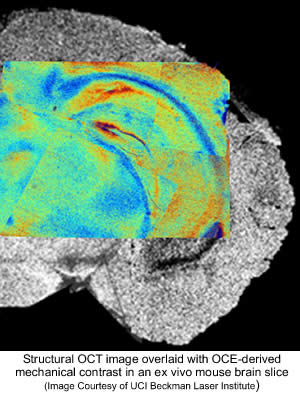
malignant and normal tissues, wherein OCE demonstrates superior contrast
compared to conventional structural OCT imaging. There is a strong interest in
accelerating OCE visualization for intraoperative use. By leveraging
differences in the Young's modulus* of tumor components, OCE can produce images
that closely resemble histological images. Unlike traditional histological
techniques, which are invasive, time-consuming, and labor-intensive, OCE can be
conducted on freshly resected tissue samples and even performed in
vivo.
(*Young's modulus is a measure of
the ability of a material to withstand changes in length when under lengthwise
tension or compression).
OCE Research at UC Irvine's Beckman
Laser Institute
Researchers at UC Irvine's Beckman Laser Institute have
considerable experience with OCE/OCT possibilities.
According to Fengyi
Zhang, Ph.D Graduate Student with the Beckman Laser Institute, "We have focused
on two destinations of OCE: a) Visualization of local movement and strains in
biological tissue; and b) Visualization of elasticity of the tissue with
mechanically produced deformations"
"The OCE technique is operable for a
broad class of sufficiently soft biological tissues, even such tissues as
cartilage," continued Dr. Zhang. "Previously, obtained strain and elasticity
maps for such materials were obtained using mechanical testing. In contrast,
OCE enables imaging in real-time."
In ophthalmology, OCE could be
utilized to characterize the mechanical properties of the cornea to diagnose
related ocular disease. With Dermatology, the elasticity of skin could indicate
related pathologies. OCE technology could detect differences in stiffness of
human skin layers in vivo. Oncological imaging ex vivo of excised tissues from
different sample regions with different stiffness could be highlighted in a 2D
depth-resolved elastogram. To improve management of atherosclerosis, OCE could
be utilized to monitor the stability of plaque by mechanical characterization
of the arterial wall.
Vibration Isolation
Maintaining the
micron-level precision needed for the OCE technique at the Beckman Laser
Institute was compromised due to low-frequency vibrations originating from the
building's air conditioning system, elevator movement and other facility
operations.
"We were using an air table to help reduce these
low-frequency vibrations, but with little success," explained Dr. Zhang. "Our
data sets were being compromised."
"The problem was resolved however,
when our laboratory was awarded a complementary Negative-Stiffness vibration
isolation platform," said Dr. Zhang, in reference to being a winner of Minus
K's Educational Vibration Isolator Giveaway.
Full
article...
|
|
|
Standard
and Custom Vibration Isolation with Better Performance than Active Systems
Cutting Edge Vibration Isolation for use in...
|
|
|
|
|
Previous
Newsletters
|

 |
|
|