![]()
SPIE International Society of Optical Engineering - February 1991
Vibration
Control in Microelectronics, Optics and Metrology
Negative-Stiffness-Mechanism Vibration Isolation
Systems
David L. Platus
Minus K Technology
11775 Gateway Boulevard, #6, Los Angeles, CA 90064 USA
ABSTRACT
A new type of vibration isolation system*
offers significant improvement in performance compared with
current state-of-the-art systems. The system uses negative-stiffness
mechanisms to cancel the stiffness of a spring suspension.
Reduction in stiffness magnifies the damping inherent in
the system creating a practical means for achieving high
hysteretic damping. The result is a simple, compact 6-DOF
passive isolation system capable of system resonant frequencies
below 0.2 Hz and first isolator resonances above 100 Hz.
Resonant transmissibilities below 1.4 can be achieved with
transmissibilities at the higher frequencies close to that
of the ideal undamped system. The negative-stiffness mechanisms
can cancel the stiffness of power cables, hoses or other
lines connected to payloads. This paper develops the theory,
describes typical configurations and summarizes lest data
with prototype systems.
1. THEORY OF OPERATION
1.1 Vertical-motion isolation
A typical vertical-motion isolator uses a conventional spring
to support the payload weight and a negative-stiffness mechanism
(NSM) ("snap-through" or "over-center"
mechanism) to cancel some or all of the stiffness of the
spring, thereby producing low or zero net vertical stiffness.
This approach has been used successfully to simulate zero
gravity in the testing of large space structures (1-2).
Its use in 6-DOF vibration isolation systems as described
in this paper is unique.
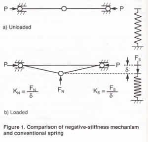 An NSM is illustrated
in Figure 1 and is compared with a conventional spring.
The NSM consists of two bars hinged at the center,
supported at their outer ends on pivots which are
free to move horizontally, and loaded in compression
by opposing forces P. For this example, motions are
constrained to the plane of the paper. In Figure l(a)
the bars arc aligned and arc in a stale of unstable
equilibrium (the center position of the NSM). In Figure
l(b), the center hinge is displaced downward an amount
An NSM is illustrated
in Figure 1 and is compared with a conventional spring.
The NSM consists of two bars hinged at the center,
supported at their outer ends on pivots which are
free to move horizontally, and loaded in compression
by opposing forces P. For this example, motions are
constrained to the plane of the paper. In Figure l(a)
the bars arc aligned and arc in a stale of unstable
equilibrium (the center position of the NSM). In Figure
l(b), the center hinge is displaced downward an amount ![]() and is held in equilibrium by the force FN which opposes the displacement. For small values of
and is held in equilibrium by the force FN which opposes the displacement. For small values of ![]() ,
a linear relationship exits between FN and
,
a linear relationship exits between FN and ![]() which is expressed by the negative stiffness KN.
The behavior of a conventional spring is also shown,
unloaded in Figure l(a) and deflected an amount
which is expressed by the negative stiffness KN.
The behavior of a conventional spring is also shown,
unloaded in Figure l(a) and deflected an amount ![]() by the force FS in Figure l(b).
Here, the force FS acts in the
direction of the displacement
by the force FS in Figure l(b).
Here, the force FS acts in the
direction of the displacement ![]() to hold the deflected spring in equilibrium, and the
ratio of FS to
to hold the deflected spring in equilibrium, and the
ratio of FS to ![]() is the positive stiffness KS.
is the positive stiffness KS.
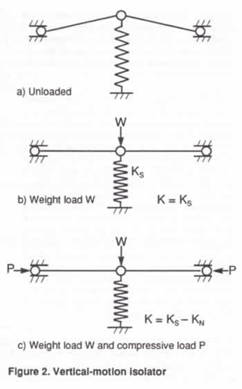
The spring and the NSM are combined to produce the
vertical-motion isolator shown in Figure 2. The isolator
is shown unloaded in Figure 2(a). In Figure 2(b),
a weight load W deflects the spring to the center
position of the isolator. The vertical stiffness of
the system in Figure 2(b) is the spring stiffness.
In Figure 2(c), forces P arc applied to the bars,
creating the NSM which cancels some or all of the
spring stiffness. This is the operating condition
of the system. The resulting isolator stiffness is
K = KN - KS,
and can be made to approach zero while the weight
load is still supported by the spring of stiffness
KS. Flexures can be used in
place of the hinged bars and offer advantages in practical
systems. The compressive load P can be applied by
various means such as a loading screw or a piezoelectric
device.
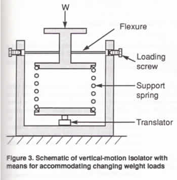
 A schematic of a vertical-motion
isolator with means for accommodating changing weight
loads is shown in Figure 3. This isolator uses flexures
and loading screws. A translator raises and lowers
the base of the spring in order to maintain the
center position of the isolator within specified
limits. Automatic leveling can be provided by controlling
the translator with limit switches or with signals
from a displacement transducer.
A schematic of a vertical-motion
isolator with means for accommodating changing weight
loads is shown in Figure 3. This isolator uses flexures
and loading screws. A translator raises and lowers
the base of the spring in order to maintain the
center position of the isolator within specified
limits. Automatic leveling can be provided by controlling
the translator with limit switches or with signals
from a displacement transducer.
1.2 Horizontal-motion isolation
Horizontal-motion isolation can be provided by a
set of flexible columns or beam-columns that behave
as springs combined with NSMs. This is illustrated
in Figure 4 with a planar example in which a payload
is supported on two flexible columns. The displaced
position in response to horizontal excitations is
shown in Figure 4(a). The payload displaces without
significant rotation because the columns are very
stiff in the vertical direction compared with their
stiffness in the horizontal direction. The horizontal
stiffness can be made near zero by designing the
columns to be loaded to approach their critical
buckling loads, thereby producing very low natural
frequencies for horizontal vibrations.
The buckling mode of the system is also generally indicated
by the deformed shape illustrated in Figure 4(a). As the
system collapses, the payload displaces horizontally and
downward. The addition of stops to limit horizontal displacements
produces a system that is fail-safe against collapse due
to inadvertent overload. Limiting the horizontal displacements
of the payload to small values changes the buckling mode
and increases the buckling strength nominally by a factor
of four. Of course, the system does not isolate when the
payload is against the stops.
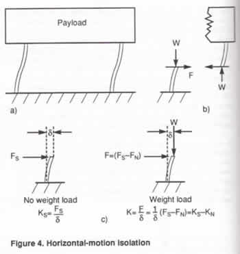 This approach makes use of the
"beam-column effect," i.e., the reduction
in bending stiffness of a beam-column due to the
axial load. The beam-columns in the isolation system
of Figure 4 are equivalent to two fixed-free columns,
as illustrated in Figure 4(b). Consider the fixed-free
column of Figure 4(c). Without weight load, the
beam-column is simply a cantilever beam with lateral
(horizontal) end load, and acts as a spring with
horizontal stiffness KS. The weight load W produces
bending moments on the laterally-loaded beam, proportional
to the deflection 8. so that less lateral force
is required to produce 8. This behavior is equivalent
to that of a spring of stiffness KS combined with
an NSM having negative stiffness of magnitude KN
that subtracts from the stiffness KS. As W approaches
the critical buckling load, K^ approaches Ks and
the net horizontal stiffness of the beam-column
approaches zero.
This approach makes use of the
"beam-column effect," i.e., the reduction
in bending stiffness of a beam-column due to the
axial load. The beam-columns in the isolation system
of Figure 4 are equivalent to two fixed-free columns,
as illustrated in Figure 4(b). Consider the fixed-free
column of Figure 4(c). Without weight load, the
beam-column is simply a cantilever beam with lateral
(horizontal) end load, and acts as a spring with
horizontal stiffness KS. The weight load W produces
bending moments on the laterally-loaded beam, proportional
to the deflection 8. so that less lateral force
is required to produce 8. This behavior is equivalent
to that of a spring of stiffness KS combined with
an NSM having negative stiffness of magnitude KN
that subtracts from the stiffness KS. As W approaches
the critical buckling load, K^ approaches Ks and
the net horizontal stiffness of the beam-column
approaches zero.
A schematic of a horizontal-motion isolation system
that passively accommodates changing weight loads
while maintaining a fixed isolation system natural
frequency is shown in Figure 5. The payload is supported
on two sets of flexible columns pre-loaded with
axial load Q. Each set has an upper and a lower
column. The lower column supports its part of the
weight load plus the axial pre-load. The upper column
supports only the axial pre-load.
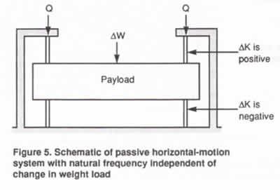 Consider, for example,
the effect of an increase in payload weight. Because
of the axial flexibility of the columns and other
flexibility in the system, the increase in payload
weight increases the axial load on the lower column
and decreases (he axial load on the upper column.
The increase in axial load on the lower column increases
the negative-stiffness effect in the lower column
reducing its horizontal stiffness; the decrease in
axial load on the upper column decreases the negative-stiffness
effect in the upper column increasing its horizontal
stiffness. By proper sizing of the upper and lower
columns, the system can be designed so that the horizontal
stiffness changes in proper proportion to the change
in payload weight so that the natural frequency remains
unchanged.
Consider, for example,
the effect of an increase in payload weight. Because
of the axial flexibility of the columns and other
flexibility in the system, the increase in payload
weight increases the axial load on the lower column
and decreases (he axial load on the upper column.
The increase in axial load on the lower column increases
the negative-stiffness effect in the lower column
reducing its horizontal stiffness; the decrease in
axial load on the upper column decreases the negative-stiffness
effect in the upper column increasing its horizontal
stiffness. By proper sizing of the upper and lower
columns, the system can be designed so that the horizontal
stiffness changes in proper proportion to the change
in payload weight so that the natural frequency remains
unchanged.
Changes in the pre-load Q change the negative-stiffness
effect in the upper and lower columns in the same direction,
thereby providing an independent means for adjusting the
system horizontal stiffness and resonant frequency.
1.3 Damping
Damping is required to limit the isolation system resonant
responses. Reduction in stiffness with the NSM magnifies
the damping inherent in the system, creating a practical
means for achieving high hysteretic damping. High hysteretic
damping is more desirable than high viscous damping because
it can limit resonant responses without significantly reducing
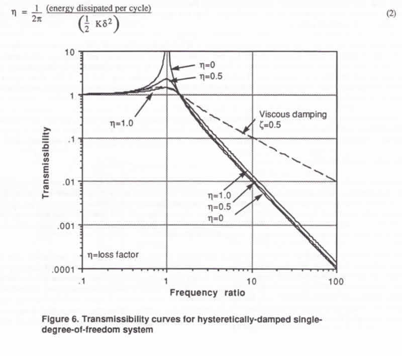
isolation efficiencies at the higher frequencies. This is
illustrated by the transmissibility curves shown in Figure
6 for a hysteretically-damped system. For example, with
a loss factor of 1.0, the resonant transmissibility is 1.4
and the transmissibilities at higher frequencies deviate
only slightly from the ideal undamped curve. For comparison,
a transmissibility curve is shown for a viscously-damped
system that gives the same resonant transmissibility of
1.4 (the viscous critical damping ratio is 0.5). The difference
in transmissibilities between the viscously-damped and the
hysteretically -damped systems at the higher frequencies
is quite dramatic considering the log scale used in the
figure.
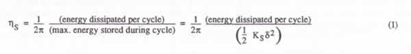
Magnification of the damping by reduction of the stiffness with the NSM can be explained as follows: Consider an ordinary spring with stiffness Kg and loss factor 1)5, supporting a mass and vibrating harmonically with displacement amplitude 5. The loss factor is related to the energy dissipated in the spring and the energy stored in the spring by,
The same basic relationship applies to the isolation system whose stiffness has been reduced from Ks to K by an NSM. The resulting isolation system loss factor is.
As the net stiffness K is reduced by the NSM, the maximum
elastic energy stored during the cycle, and associated
with ![]() ,
is diminished, but the energy dissipated per cycle is
not diminished. The energy dissipated per cycle is the
energy dissipated t" the positive spring, and can
be expressed by Equation (1). Combining Equations (1)
and (2) gives.
,
is diminished, but the energy dissipated per cycle is
not diminished. The energy dissipated per cycle is the
energy dissipated t" the positive spring, and can
be expressed by Equation (1). Combining Equations (1)
and (2) gives.
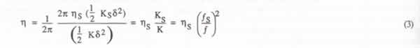
Thus, the loss factor for the system is the spring loss
factor multiplied by the ratio of spring stiffness to
system net stiffness. It is also equal to the spring loss
factor multiplied by the square of the ratio of system
resonant frequency ![]() s,
based on the spring stiffness, to the system resonant
frequency
s,
based on the spring stiffness, to the system resonant
frequency ![]() based on the reduced stiffness.
based on the reduced stiffness.
A large magnification in damping is possible in a typical
NSM isolation system. For example, consider a system in
which the positive springs alone give a resonant frequency
of 5 Hz (corresponding to Figure 2(b)), and with the NSM,
a resonant frequency of 0.5 Hz. According to Equation
(3) the isolation system loss factor is equal to the spring
loss factor multiplied by 100. For example, one percent
structural damping in the spring would produce 100% structural
damping in the isolation system.
There are benefits from adding damping to the suspension
system, particularly in the form of high-damping viscoelastic
materials. Consider a suspension of steel springs and
a viscoelastic damper. The stiffness of the system is
the sum of the spring stiffness and the damper stiffness,
but essentially all of the damping comes from the viscoelastic
damper. By adding negative stiffness with an NSM equal
in magnitude to the stiffness of the steel springs, the
resulting suspension behaves dynamically as though the
payload were suspended on only the damper. With this approach,
very low resonant frequencies and high damping can be
achieved in compact systems.
The damping behavior of the viscoelastic materials typically
falls between the viscous and the hysteretic curves of
Figure 6. Loss factors for some of these materials exceed
1.0 over certain ranges of temperature and frequency,
and manufacturers are able to tailor their materials to
particular ranges of interest. Materials can be produced
with loss factors exceeding 1.0 at room temperatures and
the low frequencies of interest for vibration isolation,
e.g., 0.2 to 1.5 Hz. Thus, system resonant transmissibilities
lower than 1.4 and transmissibilities at the higher frequencies
close to that of the ideal undamped system can be achieved
in practical systems.
The stiffness of the system can be reduced below that
of the damping material alone, producing system resonant
transmissibilities significantly lower than 1.4. However,
under these conditions in totally passive systems a creep
instability can occur. By retaining some positive stiffness
from the mechanical suspension the system is made inherently
stable.
1.4 Isolation system performance
The performance of real NSM isolation systems that we
have built and tested closely approaches the behavior
shown by the curves of Figure 6 up to frequencies at which
isolator resonances (frequencies at which the isolator
structure itself resonates) occur. Because these isolators
arc simple, compact elastic structures, their isolator
resonances arc readily predictable and can be kept al
high frequencies by proper design. Design studies supported
by tests with prototype isolators indicate that isolator
resonances can be kept above 100 Hz in practical 6-DOF
systems with isolation system resonances (frequencies
at which the system of payload and suspension resonates)
as low as 0.2 Hz or lower.
System resonances in the range of 0.5 to 1.5 Hz are of
interest for a wide range of applications, particularly
with low system resonant response, near-hysteretic-damping
behavior and isolator resonances above 100 Hz. With high-damping
viscoelastic materials currently available, resonant transmissibilities
as low as 1.4 arc achievable with practical passive NSM
isolation systems. Even better performance can be achieved
with automatic centering systems utilizing actuators controlled
by signals from displacement or velocity sensors. Also,
because performance of these isolators is based on deformation
of simple elastic structures and viscoelastic materials,
performance is not degraded (as in conventional pneumatic
isolators) by micro-motions typical of laboratory floors
and fabrication rooms.
2. SYSTEM CONFIGURATIONS
The isolators described above for handling vertical and horizontal vibrations can be combined to produce various configurations of 6-DOF isolators and isolation systems.
2.1 Passive systems
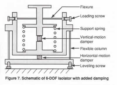 A schematic of a compact passive 6-DOF isolator with
added damping is shown in Figure 7. This isolator
His within a somewhat conventional space, with height
and diameter approximately equal. Design studies indicate
size envelopes for this configuration comparable to
pneumatic isolators that support the same weight loads.
Other configurations depart radically from the conventional
shape, including low-profile configurations that can
optimize the use of limited space in laboratories
and fabrication rooms.
A schematic of a compact passive 6-DOF isolator with
added damping is shown in Figure 7. This isolator
His within a somewhat conventional space, with height
and diameter approximately equal. Design studies indicate
size envelopes for this configuration comparable to
pneumatic isolators that support the same weight loads.
Other configurations depart radically from the conventional
shape, including low-profile configurations that can
optimize the use of limited space in laboratories
and fabrication rooms.
NSM suspension systems are applicable to a very wide
range of weight loads. Added weight is not required
in order to achieve very low resonant frequencies,
nor are the systems limited by very large weights.
For example, very low frequencies can be achieved
with a small isolated platform that supports a microscope
and with systems that support a 3000 lb. photolithography
machine or an entire fabrication room floor.
2.2 Active and automatic leveling systems
![]() An important feature of NSM systems is their capability
for stiffness and frequency adjustment through adjustment
of the NSMs. For example, combining the isolators
of Figures 3 and 5 with a servo system to control
the vertical-motion translator can produce an automatic
leveling system in which the horizontal-motion resonant
frequency is insensitive to changes in payload weight.
By using the servo system to control the vertical-motion
NSM, the vertical-motion resonant frequency can also
be made insensitive to changes in payload weight.
As another example, consider step-and-repeat systems
with stages that arc accelerated and decelerated (photolithography
machines, CMMs, etc.) Feed-forward control systems
can control the NSMs in order to stiffen the system
during stage acceleration and deceleration and soften
the system during exposures or measurements.
An important feature of NSM systems is their capability
for stiffness and frequency adjustment through adjustment
of the NSMs. For example, combining the isolators
of Figures 3 and 5 with a servo system to control
the vertical-motion translator can produce an automatic
leveling system in which the horizontal-motion resonant
frequency is insensitive to changes in payload weight.
By using the servo system to control the vertical-motion
NSM, the vertical-motion resonant frequency can also
be made insensitive to changes in payload weight.
As another example, consider step-and-repeat systems
with stages that arc accelerated and decelerated (photolithography
machines, CMMs, etc.) Feed-forward control systems
can control the NSMs in order to stiffen the system
during stage acceleration and deceleration and soften
the system during exposures or measurements.
2.3 Retrofit devices
The NSMs described above can be used to retrofit existing
isolation systems in order to reduce system resonant
frequencies and/or to increase system damping. A schematic
of a retrofit device with added damping is illustrated
in Figure 8. A set of devices is connected to the
existing system between the payload and ground without
disturbing the system. Adjustment of the loading screws
adjusts the frequencies and damping to the desired
levels.
3. TEST RESULTS WITH PROTOTYPE SYSTEMS
Prototype systems have been built and tested, including
an undamped vertical-motion system and damped and undamped
horizontal-motion systems. An undamped horizontal-motion
system is shown in Figure 9. A small 6-DOF isolated platform
ii being fabricated and will soon be tested.
![]() The undamped
systems demonstrated system resonant frequencies below
0.2 Hz, as determined by visual observations. The
increase in system damping with reduction in system
stiffness was also apparent from observation of the
decay of the free vibrations. Transmissibility tests
were run on some of the horizontal-motion systems.
Typical test data are shown in Figures 10 to 15. The
ideal undamped curves arc shown in Figures 10 and
11 for comparison.
The undamped
systems demonstrated system resonant frequencies below
0.2 Hz, as determined by visual observations. The
increase in system damping with reduction in system
stiffness was also apparent from observation of the
decay of the free vibrations. Transmissibility tests
were run on some of the horizontal-motion systems.
Typical test data are shown in Figures 10 to 15. The
ideal undamped curves arc shown in Figures 10 and
11 for comparison.
In the damped horizontal-motion systems the payload
is supported on flexible steel columns with viscoelastic
dampers connected in parallel. For the transmissibility
tests, the columns were loaded close to their critical
buckling loads so the systems behaved dynamically
almost as though the payload were supported on only
the dampers. Standard off-the-shelf damping materials
were used which generally arc not optimum for the
room-temperature low-frequency applications of interest.
Optimum formulations of these materials can provide
loss factors exceeding 1.0 and resonant transmissibilities
below 1.4 at low frequencies and room temperatures.
The system of Figure 11 was first tested without the
dampers and tuned to a system resonant frequency of
0.2 Hz. The dampers were then connected, raising the
frequency to 0.73 Hz. Different damping materials
were used for the systems of Figures 10 and 11, neither
of which is optimum from the standpoint of maximum
damping at system resonance.
![]()
![]()
![]()
The transmissibility curves of Figures 10 and 11 were
obtained using forced vibrations from electrodynamic
shakers, v. inputs in the milli-g range. The curves
of Figures 12 to 15 were determined from low-amplitude
ambient vibrations laboratory floor with a measured
input of 7.3 x 10* g RMS from DC to 15 Hz. A third damping
material was used for systems of Figures 13 and 15 which
does exhibit loss factors exceeding 1.0 at the system
resonant frequencies. These ambient vibration transmissibility
curves were measured by Dr. R.L. Nigbor of Agbabian
Associates. The method used for these measurements is
described in his paper, "Accurate characterization
of low-level vibration environments using seismological
sensors and systems," also in these proceedings.
The undamped system of Figure 12 has a resonant frequency
around 0.4 Hz. Adding dampers to this system gives the
system of Figure 13 with a resonant frequency of 0.8
Hz and a resonant transmissibility of 1.2. The undamped
system of Figure 14 h_ a resonant frequency of 0.9 Hz.
Adding dampers gives the system of Figure 15 with a
resonant frequency of 4.3 Hz and a resonant transmissibility
of 1.3. For the particular damping material used in
the systems of Figures 13 and 15. transmissibility behavior
is close to the ideal viscous curve shown in Figure
6.
4. SUMMARY OF KEY FEATURES
The following are key features of negative-stiffness-mechanism vibration isolation systems:
-
Passive
-
Compact
-
No air
-
6-DOF isolation
-
Simple automatic leveling for changing weight loads
-
Can provide system resonant frequencies below 0.2 Hz and first isolator resonances above 100 Hz
-
Can provide system resonant transmissibilities below 1.4 with transmissibilities at higher frequencies close to the ideal undamped system
-
Not degraded by micro-motion inputs
-
Can cancel the stiffness of power lines, hoses, cables, etc., connected to payloads
-
Can retrofit existing systems to reduce frequencies and increase damping without disturbing the existing systems
-
Isolation system stiffness can be adjusted manually or automatically
-
Applicable to very small and very large payloads
5. ACKNOWLEDGEMENT
6. REFERENCES
1. R. Ikegami, et. al., "Zero-G Ground Test Simulation
Methods," Proceedings of the 11th Aerospace Testing
Seminar pp. 215-225, The institute of Environmental Sciences,
Manhattan Beach, CA. October 11-13, 1988.
2. S.E. Woodard and J.M. Housner, "Nonlinear Behavior
of a Passive Zero-Spring-Rate Suspension System,"
J Guidance, American Institute of Aeronautics and Astronautics,
Vol. 14, No. 1, pp. 84-89, Jan.-Feb. 1991.
|