![]()
Laboratory Equipment - July 2013
Microscopy
Technology Spurs Expansion of AFM Scanning Range
Increased scan size of AFMs allows high-resolution imaging of new samples types
By:Jim McMahon for Minus K Technology, Inglewood, Calif.
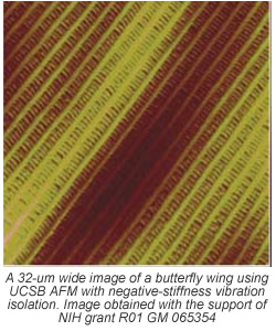
With its development in 1986, and subsequent commercial introduction in 1989, the atomic force microscope (AFM) has become one of the foremost tools for imaging and measuring materials and cells on the nanoscale. Revealing sample details at the atomic level, with resolution on the order of fractions of a nanometer, the AFM is instrumental for imaging an array of applications, such as defining surface characterizations, lithography, data storage and manipulation of atoms and nano-sized structures on a variety of surfaces.
The atomic force microscope uses a sharp tip (probe), with a radius of curvature on the order of nanometers, attached to the end of a tiny cantilever used to scan across a sample surface to image its topography and material properties. When the tip is brought into proximity of a sample surface, forces between the tip and the surface lead to a deflection of the cantilever. This deflection is recorded using, typically, a laser beam that is reflected from the top surface of the cantilever to a photo-sensitive detector. The resultant change of position of the cantilever permits characteristics such as mechanical, electrostatic, magnetic, chemical and other forces to be precisely measured by the AFM. These characteristics are displayed in a three-dimensional surface profile of the sample (in the X, Y and Z axes}-an advantage that the AFM can provide compared to other microscopy techniques, such as the scanning electron microscope (SEM), which delivers a two-dimensional image of a sample (in the X and Y axis).
Expanding capability, scanning range
Since the release of the first commercial AFM about 25 years ago, technology advances have been integrated into AFMs to improve their performance. One of these has been expanding the AFMs ability to image biological samples in an aqueous buffer, and provide a range of physical data for the sample-a key capability that not all microscopy techniques can deliver. Another has been to increase the imaging speed of AFMs. Unlike SEMs, which are capable of scanning in near real-time, conventional AFMs, prior to about five years ago, required between one and 100 minutes to obtain a high-resolution image. With the introduction of high-speed AFM systems, imaging speeds can now be achieved that are three orders A of magnitude of three times faster than with previous AFMs.
Since the AFM was designed for imaging rnicro-structures on the micrometer and nanometer scale, its single scan image size is somewhat limited to a maximum scanning area of about l00 x100 micrometers. When researchers require a larger scale image, they typically use a SEM, which can produce quality images on a wide range of magnifications and sample sizes in the X and Y axis. In one pass, the SEM can image an area on the order of square millimeters, and with a depth of field of millimeters.
Within the past several years, however, research into AFM design, conducted by the Paul Hansma Research Group, Department of Physics, at the Univ.. of California, Santa Barbara, has demonstrated success with AFM imaging of large-scale samples at nanoscale resolutions, while extending the range of the Z-axis. The lab's current technical challenge is to design an AFM system that can significantly extend the scan range, while operating at a reasonable imaging speed with acceptable image resolution and linearity.
The Hansma lab's objective for expanding the scan range of its latest prototype AFM design is directed toward exploring the molecular origins of fracture resistance in mineralized tissues, primarily bone. Because of the limited range of AFMs, many critical measurements of large-scale bone fractures have not been produced. Typically, SEM is used to show the entirety of a bone crack, but it is unable to provide the detailed information that an AFM is capable of producing, nor to image bone matrix material properties in a natural hydrated fracture process.
Bone fracture and fracture surfaces on the microscale and nanoscale have been imaged with AFM," says Hansma.. "but many microfractures remain beyond the reach of AFM, such as those created by bone diagnostic instruments like the reference point indentation (RPI) instrument."
The RPI is an instrument that creates a small indent in the bone to determine its fracture resistance and gathers data on the depth and forces of the indent.
"By imaging these indents and the associated rnicrofractures, we have an opportunity to make real progress in understanding the nanoscale mechanisms that contribute to fracture resistance," explained Hansma.
The large height difference between the bone surface and the depth of the fracture is impossible for current AFMs to image completely; both because of the insufficient range and the probe length. To image at the extreme depths necessary in large-scale cracks and deep microcracks, the AFM must have a Z-range of at least 200 microns and a cantilever up long enough to probe the crack."
As the vertical movement of the tip was increased, however, it brought into play more of a possibility for vibration. This issue was solved with the incorporation of negative-stiffness vibration isolation.
 Improving vibration isolation
The need for more precise vibration isolation with atomic force microscopy as becoming more critical as resolutions continue to bridge from micro to nano. AFM systems are extremely susceptible to vibrations from the environment. When measuring very few angstroms or nanometers of displacement, an absolutely stable surface must be established for the instrument. Any vibration coupled into the mechanical structure of die instrument will cause vertical and/or horizontal noise and bring about a reduction in the ability to measure with the highest resolution. The vertical axis is the most sensitive for AFMs, but they are also quite sensitive to vibrations in the X and Y axes.
Developed and patented by Minus K Technology; negative-stiffness isolators provide a unique capability to the field of AFM research. They employ a completely mechanical concept in low-frequency vibration isolation, while achieving a high level of isolation in multiple directions.
In negative-stiffness vibration isolation, vertical-motion isolation is provided by a stiff spring that supports a weight load., combined with a negative-stiffness mechanism. The net vertical stiffness is made very low without affecting the static load-supporting capability of the spring. Beam-columns connected in series with the vertical-motion isolator provide horizontal-motion isolation. A beam-column behaves as a spring combined with a negative-stiffness mechanism. The result is a compact passive isolator capable of very low vertical and horizontal natural frequencies and very high internal structural frequencies.
The result is an isolator that provides 0.5 Hz isolation performance vertical and 0.5 Hz horizontal, using a totally passive mechanical system-no air or electricity required.
Negative-stiffness isolators resonate at 0.5 Hz. At this frequency there is almost no energy present. It would be very unusual to find a significant vibration at 0.5 Hz. Vibrations with frequencies above 0.7 Hz (where negative-stiffness isolators begin isolating) are rapidly attenuated with increase in frequency.
We llike the vibration isolation to be at 0.5 Hz, which we can achieve with the negative-stiffness table,' says Hansma. "Not so much because of the vibrations at that frequency; which are minimal., but because 0.5 Hz is 16% more resistant to transmitting vibrations at a building resonance of 10 or 20 Hz than compared with a resonant frequency of 2 Hz, which would be found with air tables."
In contrast, air tables, as vibration isolation systems, deliver limited isolation vertically and less isolation horizontally. They can make vibration isolation problems worse since they have a resonant frequency that can match that of floor vibrations. Air tables will actually amplify; instead of reduce, vibrations in a typical range of 2 to 7 Hz.
Using combined AFM and RP1 techniques, and supported by passive negative-stiffness vibration isolation system, Hansma's lab has been able to achieve scan ranges exceeding one millimeter, an order of magnitude larger in the Z-axis than any commercially available AFM-
The AFM/RPI system has also proved capable of exploring die molecular origins of fracture resistance in bone tissues to more than 1 mm2, with good resolution and linearity.